Vega VEGABAR 53 Foundation Fieldbus Bedienungsanleitung
Stöbern Sie online oder laden Sie Bedienungsanleitung nach Ausrüstung Vega VEGABAR 53 Foundation Fieldbus herunter. VEGA VEGABAR 53 Foundation Fieldbus User Manual Benutzerhandbuch
- Seite / 64
- Inhaltsverzeichnis
- LESEZEICHEN
- Operating Instructions 1
- VEGABAR 53 1
- Contents 2
- 1 About this document 4
- 2 For your safety 5
- 2 For your safety 6
- 3 Product description 7
- 3.2 Principle of operation 8
- 3.3 Operation 9
- 3 Product description 10
- 4 Mounting 12
- 4.3 Mounting steps 14
- 5 Connecting to power supply 16
- 5.2 Connection procedure 17
- 5 Connecting to power supply 18
- 36724-EN-130321 21
- Connection compartment 21
- Wiring plan 21
- Electronics compartment 22
- 1 Voltage supply 25
- 6.1 Short description 26
- 6.3 Adjustment system 27
- 6.4 Setup steps 28
- Selection options: °C, °F 30
- Max. adjustment 31
- +100.0 % 31
- +1000.0 mbar 31
- 0000.0 mbar 31
- 6.5 Menu schematic 35
- 7.1 Connect the PC 38
- 8.1 Maintain 40
- 8.2 Rectifyfaults 40
- 8.4 Software update 42
- 8.5 Instrument repair 42
- 9 Dismounting 44
- 10 Supplement 45
- -40°C -20°C 49
- 40°C 60°C 80°C 49
- TB Transducer Block 54
- 10.3 Dimensions 56
- VEGABAR53,threadedtting 58
- GF/GK GC/GH 58
- Tuchenhagen Varivent DN 32 59
- VEGABAR53,hygienictting3 60
- RB RC RD 60
- 10.5 Trademark 62
- Printing date: 64
Inhaltsverzeichnis
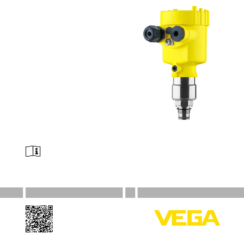
Operating InstructionsPressure transmitter with metallic measuring cellVEGABAR 53Foundation FieldbusDocument ID: 36724
103 Product descriptionVEGABAR 53 • Foundation Fieldbus36724-EN-130321The delivery must be checked for completeness and possible transit damage immedi
113 Product descriptionVEGABAR 53 • Foundation Fieldbus36724-EN-130321The protective cover protects the sensor housing against soiling and intense hea
124 MountingVEGABAR 53 • Foundation Fieldbus36724-EN-1303214 Mounting4.1 General instructionsMake sure that all parts of the instrument coming in dir
134 MountingVEGABAR 53 • Foundation Fieldbus36724-EN-13032121212112Fig. 4: Position of the lter element1 Filter element2 Blind plugCaution:Duetot
144 MountingVEGABAR 53 • Foundation Fieldbus36724-EN-130321Instrumentsintheversion"Oil and grease free for oxygen"shouldbe unpacked ju
154 MountingVEGABAR 53 • Foundation Fieldbus36724-EN-13032190 mm (3.54")R 3,5 mm(0.14")3mm(0.12")70 mm (2.76")8 mm(0.32")93 m
165 Connecting to power supplyVEGABAR 53 • Foundation Fieldbus36724-EN-1303215 Connecting to power supply5.1 Preparing the connectionAlways keep in
175 Connecting to power supplyVEGABAR 53 • Foundation Fieldbus36724-EN-130321low frequency potential equalisation currents are thus suppressed, butth
185 Connecting to power supplyVEGABAR 53 • Foundation Fieldbus36724-EN-130321Fig. 7: Connection steps 6 and 7Proceed as follows:1. Loosen the four sc
195 Connecting to power supplyVEGABAR 53 • Foundation Fieldbus36724-EN-130321Information:The cable gland can be mounted in three positions each displa
2ContentsVEGABAR 53 • Foundation Fieldbus36724-EN-130321Contents1 About this document1.1 Function ...
205 Connecting to power supplyVEGABAR 53 • Foundation Fieldbus36724-EN-130321I2CDisplay112 5 678Fig. 10: Wiring plan, single chamber housing1 Voltage
215 Connecting to power supplyVEGABAR 53 • Foundation Fieldbus36724-EN-130321123Display12I2CFig. 12: Connection compartment, double chamber housing1
225 Connecting to power supplyVEGABAR 53 • Foundation Fieldbus36724-EN-1303215.5 Wiring plan, double chamber housing Ex dI²C231DisplayTyp:12 5678BusS
235 Connecting to power supplyVEGABAR 53 • Foundation Fieldbus36724-EN-130321112Fig. 16: Wiring plan, Ex-d double chamber housing1 Voltage supply, si
245 Connecting to power supplyVEGABAR 53 • Foundation Fieldbus36724-EN-130321I²CDisplayTyp:12 5678BusSim.456123Fig. 19: Electronics and connection com
255 Connecting to power supplyVEGABAR 53 • Foundation Fieldbus36724-EN-130321I2CDisplay112 5 678Fig. 21: Wiring plan external electronics1 Voltage su
266 Set up with the display and adjustment module PLICSCOMVEGABAR 53 • Foundation Fieldbus36724-EN-1303216 Set up with the display and adjustment mod
276 Set up with the display and adjustment module PLICSCOMVEGABAR 53 • Foundation Fieldbus36724-EN-130321Fig. 22: Insert display and adjustment module
286 Set up with the display and adjustment module PLICSCOMVEGABAR 53 • Foundation Fieldbus36724-EN-130321 – Save value• [->] key to select: – Menu
296 Set up with the display and adjustment module PLICSCOMVEGABAR 53 • Foundation Fieldbus36724-EN-130321The actual measured value is also displayed i
3ContentsVEGABAR 53 • Foundation Fieldbus36724-EN-1303217.3 Parameter adjustment with AMS™...
306 Set up with the display and adjustment module PLICSCOMVEGABAR 53 • Foundation Fieldbus36724-EN-130321Density0001000kg/dm³6. Enter the requested d
316 Set up with the display and adjustment module PLICSCOMVEGABAR 53 • Foundation Fieldbus36724-EN-130321Iftheadjustmentrangesareexceeded,theme
326 Set up with the display and adjustment module PLICSCOMVEGABAR 53 • Foundation Fieldbus36724-EN-130321The display and adjustment module enables the
336 Set up with the display and adjustment module PLICSCOMVEGABAR 53 • Foundation Fieldbus36724-EN-130321The adjustment unit is thus switched over fro
346 Set up with the display and adjustment module PLICSCOMVEGABAR 53 • Foundation Fieldbus36724-EN-130321Proceed as follows:1. Editthembarvaluein
356 Set up with the display and adjustment module PLICSCOMVEGABAR 53 • Foundation Fieldbus36724-EN-130321ResetBasic adjustmentPeak value, measured val
366 Set up with the display and adjustment module PLICSCOMVEGABAR 53 • Foundation Fieldbus36724-EN-130321Basic adjustment▶Basic adjustment 1DisplayDia
376 Set up with the display and adjustment module PLICSCOMVEGABAR 53 • Foundation Fieldbus36724-EN-130321ServiceBasic adjustment 4DisplayDiagnostics▶S
387 Set up with PACTware and other adjustment programsVEGABAR 53 • Foundation Fieldbus36724-EN-1303217 Set up with PACTware and other adjustment prog
397 Set up with PACTware and other adjustment programsVEGABAR 53 • Foundation Fieldbus36724-EN-1303217.2 Parameter adjustment with PACTwareFurther se
41 About this documentVEGABAR 53 • Foundation Fieldbus36724-EN-1303211 About this document1.1 FunctionThis operating instructions manual provides all
408MaintenanceandfaultrecticationVEGABAR 53 • Foundation Fieldbus36724-EN-1303218 Maintenanceandfaultrectication8.1 MaintainIf the instrumen
418MaintenanceandfaultrecticationVEGABAR 53 • Foundation Fieldbus36724-EN-130321Error Cause RecticationWhen an addition-al instrument is connect
428MaintenanceandfaultrecticationVEGABAR 53 • Foundation Fieldbus36724-EN-130321The serial number is stated on the type label of VEGABAR 53 or on
438MaintenanceandfaultrecticationVEGABAR 53 • Foundation Fieldbus36724-EN-130321Youcandownloadareturnform(23KB)fromourInternethomepage
449 DismountingVEGABAR 53 • Foundation Fieldbus36724-EN-1303219 Dismounting9.1 Dismounting stepsWarning:Before dismounting, be aware of dangerous pro
4510 SupplementVEGABAR 53 • Foundation Fieldbus36724-EN-13032110 Supplement10.1 Technical dataGeneral dataPressure type Gauge pressure or gauge press
4610 SupplementVEGABAR 53 • Foundation Fieldbus36724-EN-130321 Ʋ Ground terminal 316Ti/316L Ʋ Ohmic contact Betweengroundterminalandprocesstting
4710 SupplementVEGABAR 53 • Foundation Fieldbus36724-EN-130321Input variableAdjustmentAdjustment range of the min./max. adjustment relating to the nom
4810 SupplementVEGABAR 53 • Foundation Fieldbus36724-EN-130321Nominalrange Overload capacity, max. pressureOverload capacity, min. pres-sureGauge pre
4910 SupplementVEGABAR 53 • Foundation Fieldbus36724-EN-130321 Ʋ Turn down > 5 : 1 < 0.015 % x TDDeviation with version 0.1 % Ʋ Turn down 1 : 1
52 For your safetyVEGABAR 53 • Foundation Fieldbus36724-EN-1303212 For your safety2.1 Authorised personnelAll operations described in this operating
5010 SupplementVEGABAR 53 • Foundation Fieldbus36724-EN-130321Ambient conditionsAmbient, storage and transport temperature Ʋ Standard version -40…+8
5110 SupplementVEGABAR 53 • Foundation Fieldbus36724-EN-130321Shock resistance Acceleration 100 g/6 ms19)Electromechanical data - version IP 66/IP 67C
5210 SupplementVEGABAR 53 • Foundation Fieldbus36724-EN-130321 Ʋ Min. bending radius at 25 °C/77 °F 25mm(0.985in) Ʋ Diameter approx. 8mm(0.315in
5310 SupplementVEGABAR 53 • Foundation Fieldbus36724-EN-130321 Ʋ Non-Ex instrument 12 … 32 V DC Ʋ Ex-ia instrument 12 … 24 V DCEx d instrument 12 … 32
5410 SupplementVEGABAR 53 • Foundation Fieldbus36724-EN-130321tiSimulateALARMSOutPVFIELD-VALUEMode & StatusPVF-TIMELOW-CUTOFFL-TYPEOUT-SCALEPV-SCA
5510 SupplementVEGABAR 53 • Foundation Fieldbus36724-EN-130321• secondary_value_2 – Valueaftermin/max-adjustment.SelectedasinputtoAIFBbysetti
5610 SupplementVEGABAR 53 • Foundation Fieldbus36724-EN-130321 – Highest calibrated value. For calibration of the high limit point you give the high m
5710 SupplementVEGABAR 53 • Foundation Fieldbus36724-EN-130321External housing with version IP 681265 mm(2.68")68 mm(2.68")92 mm(3.62")
5810 SupplementVEGABAR 53 • Foundation Fieldbus36724-EN-130321VEGABAR53,threadedtting23 mm(29/32")G ½ AG ½ B63 mm(2 31/64")65 mm(2 9/16&
5910 SupplementVEGABAR 53 • Foundation Fieldbus36724-EN-130321VEGABAR53,hygienictting1LA ø78 mm (3 5/64")82 mm(3 15/64")LBø 90 mm (3 35
62 For your safetyVEGABAR 53 • Foundation Fieldbus36724-EN-1303212.6 CE conformityThisdevicefulllsthelegalrequirementsoftheapplicableECgui
6010 SupplementVEGABAR 53 • Foundation Fieldbus36724-EN-130321VEGABAR53,hygienictting3RA81 mm(3 3/16")84 mm(3 3/16")84 mm(3 3/16")
6110 SupplementVEGABAR 53 • Foundation Fieldbus36724-EN-130321VEGABAR53,hygienictting4AA82 mm(3.23")ø 65 mm (2.56")ø 105 mm (4.13"
6210 SupplementVEGABAR 53 • Foundation Fieldbus36724-EN-13032110.4 Industrial property rightsVEGA product lines are global protected by industrial pr
63INDEXVEGABAR 53 • Foundation Fieldbus36724-EN-130321INDEXAAccessories – Display and adjustment module 10 – External display and adjustment unit 10
Printing date:VEGA Grieshaber KGAm Hohenstein 11377761 SchiltachGermany36724-EN-130321All statements concerning scope of delivery, application, practi
73 Product descriptionVEGABAR 53 • Foundation Fieldbus36724-EN-1303213 Product description3.1 CongurationThe scope of delivery encompasses:• VEGABA
83 Product descriptionVEGABAR 53 • Foundation Fieldbus36724-EN-1303212113105436789111214Fig. 2: Layout of the type label (example)1 Instrument type2
93 Product descriptionVEGABAR 53 • Foundation Fieldbus36724-EN-130321Power is supplied via the H1 Fieldbus. A two-wire cable according to Fieldbusspe
Weitere Dokumente für Ausrüstung Vega VEGABAR 53 Foundation Fieldbus


Verwandte Produkte und Handbücher für Ausrüstung Vega VEGABAR 53 Foundation Fieldbus
 (60 Seiten)
 (20 Seiten)
(24 Seiten)
(20 Seiten)
(24 Seiten)
 (76 Seiten)
 (20 Seiten)
 (88 Seiten)
 (24 Seiten)
© 2020, manymanuals.de. Alle Rechte vorbehalten. | 0.949 s |
 Manymanuals.com
 Manymanuals.de
 Manymanuals.fr
 Manymanuals.it
 Manymanuals.pl
 Manymanuals.cz
 Manymanuals.es
 Manymanuals-pt.com
Kommentare zu diesen Handbüchern